DualShock 2 to USB Adapter
- Category:
- Tutorials
- Author:
- Dan Farkash
- Date:
- 05/25/2025
In this tutorial we’ll be showing you how to build a Sony DualShock 2 controller to USB adapter that provides full pressure-sensitive button and rumble motor support when used with the PCSX2 emulator. NOTE: This project has only been tested with an official DualShock 2 controller, and Windows 11.
Acronyms
- SPI - Serial Peripheral Interface
- HID - Human Interface Device
- USB - Universal Serial Bus
- PC - Personal Computer
Background
The Sony DualShock 2 controller uses SPI to communicate with the PlayStation 2. In order to get the controller to interface with a computer through USB, I’ve used Microchips PIC18F4550 microcontroller. Using this microcontroller we can communicate with the DualShock 2 controller through the SPI protocol to gather all its data, and then communicate that data through USB to a PC.
I decided to use the PIC18F4550 microcontroller because there was plenty's of documentation online of other people who had used this microcontroller or a similar one from Microchip to make both a USB device and a device that could communicate with a DualShock 2 controller. Here’s links to the two main sources I used.
Creating a PIC USB HID Guide
https://www.waitingforfriday.com/?p=451
Interfacing a PIC w/ DualShock 2 Controller Guide
https://docs.google.com/document/d/1XSrNVxOWOfCggHXhkQBapbmum18elYUx/edit
If you’d like to know how to make a simple USB HID device on a PIC microcontroller from scratch, or if you’d like to know the nitty gritty on how to interface with a DualShock 2 controller, I’d click on the links above. Huge thanks to the creators of each source I used in creating this project, I’ve put a full list of all of them at the end of this page.
To get the rumble motors functional, I used a boost converter (utilizing a MAX1771CPA+ to make my life a little easier), and three AA batteries as the voltage source. Unfortunately USB 1.0 only provides up to 500 mA of current, and the paper I found (the one linked above from Kok Chee Khean) states that the rumble motors will consume 500 mA of inrush current starting up. Therefore the USB 1.0 port wouldn’t provide enough current for all the components (the microcontroller, the DualShock 2 controller, and the rumble motors). Assuming not everybody is going to have USB 2.0 or USB 3.0 (which both allow for more current), I decided to use batteries which will solely supply power for the rumble motors instead.
DualShock 2 controllers are special in that they’re built with 12 fully analog buttons.
Analog Buttons
- DPAD Right
- DPAD Left
- DPAD Up
- DPAD Down
- Triangle
- Circle
- Cross
- Square
- L1
- R1
- L2
- R2
Analog Axis
- Right Joystick X
- Right Joystick Y
- Left Joystick X
- Left Joystick Y
Only certain games will actually make use of all pressure-sensitive buttons, you can check out the full list of games that make use of them using the link below.
Communicating all analog data from our controller to a computer running a Windows OS is not a trivial task. When creating a device that utilizes Windows native HID drivers for USB devices, we’re unfortunately limited to using a maximum of 8 analog values (values that range from 0 to 255 rather than digital values that are just 0 or 1, OFF or ON), and in our case we technically need to communicate 16 analog values (12 analog buttons and 4 analog axis).
When trying to figure out a way around this problem I had a few choices. One involved using two microcontrollers each sending data each through a separate USB port and each representing a separate device to get around the analog value limit. The other solution which is more practical on the user-end (as some PCs including the one I’m typing on right now only have one USB port) would be creating a custom driver to recognize our USB device rather than making use of the native drivers Windows has readily available for USB HIDs (not an expert on drivers so I hope I didn’t botch that explanation).
Ultimately I decided that rather than breaking my head trying to figure out how to create a custom driver (although I may try to one day), I could utilize a driver (DsHidMini) already made for the DualShock 3 controller which has proven compatibility with the PCSX2 emulator for running PlayStation 2 games with all pressure-sensitive buttons. With the exception of the analog button, the DualShock 3 controller has all the same buttons that the DualShock 2 controller has. We’re able to mimic the DualShock 3 controllers firmware and thereby feed the inputs from a DualShock 2 controller into the DsHidMini driver.
Here’s a video of the adapter working with the controllers pressure sensitive buttons in action.
How To Make This For Yourself
To start off you want to build this circuit (download the PDF below of the circuit). NOTE: Don’t know how long it’ll take, but my next goal is to try to create a PCB for this circuit, which I expect to provide more benefits than just being neater and more compact (see below).
Here's a few pictures of mine.
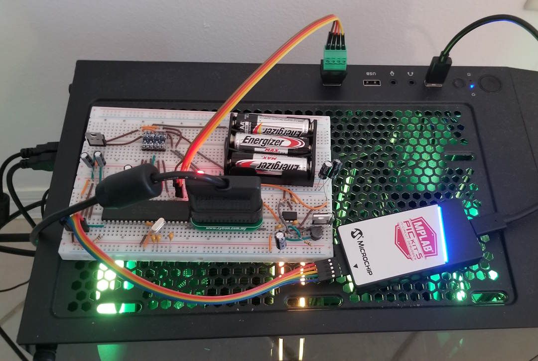
With the battery pack plugged in.
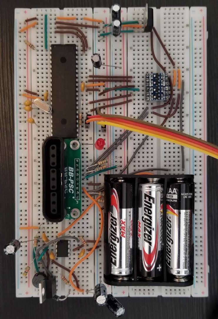
Without.
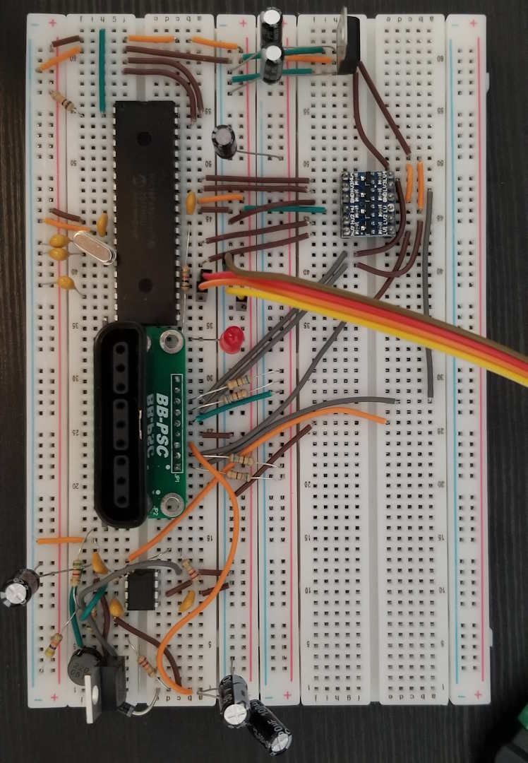
A few things to note, USB ports provide 5 Volts, while the DualShock 2 controller runs on around 3.3 Volts when connected to a PlayStation 2. For safety, despite 5 Volts seemingly working perfectly fine, I’ve decided to add a voltage regular to step 5 Volts down to 3.3 Volts for feeding power to the DualShock 2 controller as well as feeding a level converter for each signal from the microcontroller (5 Volts) to the DualShock 2 controller (3.3 Volts).
Unfortunately because our circuit spans out quite a bit being on a breadboard and not a PCB, there’s too much parasitic inductance from the wires going from the level converter to the socket for the DualShock 2 controller plug. The inductance causes the slew rate for each signal to decrease by too much which in turn causes the SPI communication between the microcontroller and DualShock 2 controller to fail. To fix this I’ve added pull-up resistors where these wires connect to the socket. Not really the most efficient as the level converter already has pull-up resistors, but for now until I make a PCB version it does the job.
BOM
Base Adapter
- 1 PIC18F4550 Microcontroller
- 1 DualShock 2 Controller Connector
- 1 LD1117V33 Voltage Regulator to 3.3V
- 1 Bi-Directional Logic Level Converter 5V to 3.3V Buck and 3.3V to 5V Boost (I used a random one from Amazon, brand WWZMDiB, not sure how other ones would but I'd imagine most MOSFET bi-directional logic level shifters would work just fine, just remember it needs to shift at least 5 I/O's)
- 1 20MHz Quartz Crystal
- 1 USB Plug
- 2 830 Point Breadboards
- 2 10KΩ Resistors (R1 and R2)
- 4 580Ω Resistors (R3, R4, R5, and R6)
- 2 100nF Capacitors (C1 & C4)
- 2 15pF Capacitors (C2 & C3)
- 1 470nF Capacitor (C5)
- 2 10µF Capacitors (C6 & C7)
- 1 PICKit (I used the PICKit 5)
- Breadboard Compatible Wiring (22AWG)
Rumble Motor Boost Converter
- 1 22µH Fixed Inductor
- 1 Schottky diode
- 1 Battery Holder/ Contact for 3 AA Batteries
- 1 MTP3055VL N-Channel MOSFET
- 1 MAX1771CPA+ Step-Up/ Step-Down DC-DC Controller
- 1 5.1KΩ Resistor (R7)
- 1 47KΩ Resistor (R8)
- 1 22.1KΩ Resistor (R9)
- 1 90KΩ Resistor (R10)
- 2 0.1µF Capacitors (C8 and C9)
- 1 100pF Capacitor (C10)
- 1 100µF Capacitor (C11)
- 1 200µF Capacitor (C12)
- 3 AA Batteries
LED D1 (Not Required)
- 1 1KΩ Resistor (R11)
- 1 Breadboard Compatible LED
I've tied links to the more special components on the BOM for convenience (just click on the items on the list). For the resistors and capacitors, I wouldn't say any of those values have to be dead-on, so long as it's close. Would recommend buying capacitor and resistor kits that include the values shown on the BOM and mixing and matching resistors and capacitors where needed to get around the value you need (you'll notice that's what I did). A jumper wire kit or spool of a single conductor breadboard compatible wire is also needed to make the connections.
After you’ve built the circuit, you’re going to need to get a PICKit to program the PIC18F4550 microcontroller. I personally used a PICKit 5, but other PICKit's should work just fine too (heard even the clones aren’t that bad).
Next you’re going to need to install the MPLAB X IDE. Just note that getting the software to connect to your PICKit for the first time can be… a real pain in the ass. For me I had to uninstall and reinstall the PICKit 5 driver, as well as restart my computer several times just to get it working.
Make a new folder for all of the files we're going to need. Install the MPLAB X project from GitHub using the link below and drag over the file named "DualShock 2 Adapter" from the compressed GitHub file into that folder.
https://github.com/farmerboy101/DualShock-2-Adapter
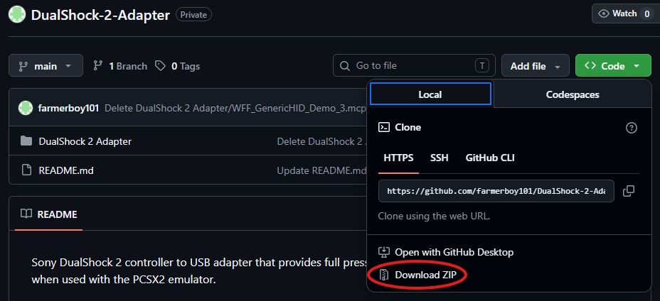
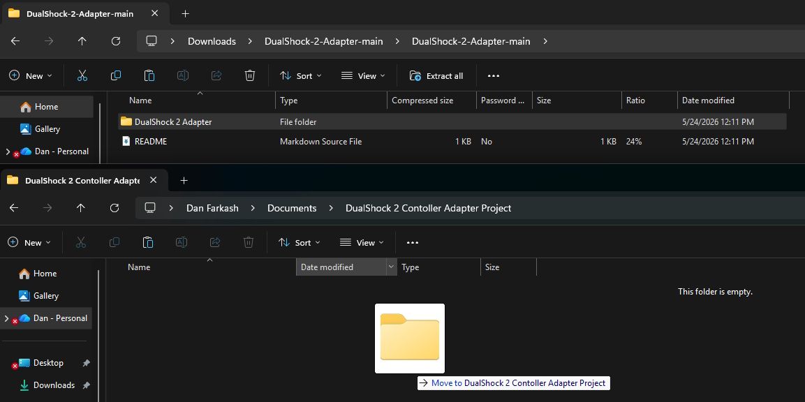
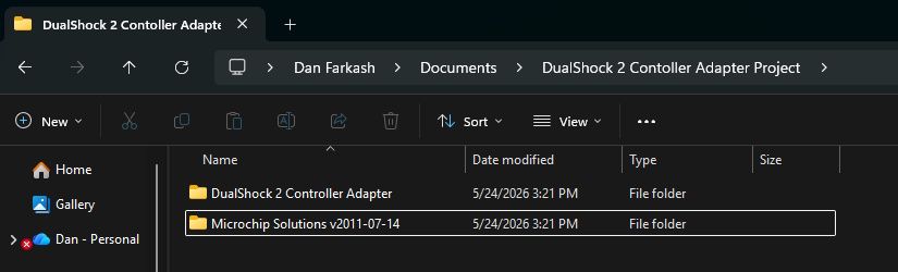
Download the Microchip Solutions v2011-07-14 library using the link below (see the "Downloads Archive" section at the bottom of the page). Put the "Microchip Solutions v2011-07-14" file into that same parent folder we have the MPLAB X project in. NOTE: You may get a window popping up blocking you from running the file (Windows Defender SmartScreen) when you first run the Microchip library installer, click More info and Run to get past it.
At this point the folder should look something like this.
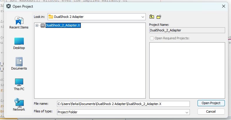
Open the "DualShock 2 Controller Adapter" project on the MPLAB X IDE using File > Open Project.
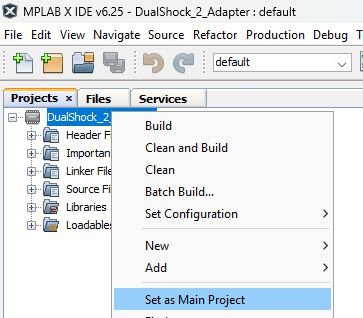
Right click on the project and hit Set as Main Project.
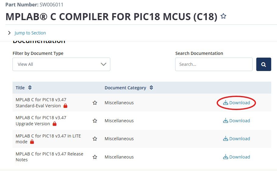
If you don't have it already you need to download the MPLAB C compiler for PIC18X microcontrollers in order to run the project and program your microcontroller, you can download it using the link below.
https://www.microchip.com/en-us/development-tool/sw006011
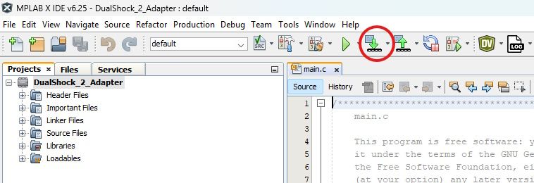
Connect your PICKit to the breadboard project you've built earlier, and connect the breadboard project to your PC through it's USB plug. If you haven't already connect the DualShock 2 controller to your breadboard project (doing this in advance, doesn't affect the microcontroller being programmed), and then hit Make and Program Device Main Project.
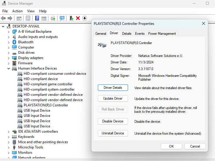
When you first connect your breadboard project, your PC may not recognize your new USB device as a DualShock 3 controller. This is because we've yet to install the DsHidMini driver. Download the DsHidMini driver using the link below (it says it won't work on anything but an official DualShock 3 controller, but I promise you this will work). NOTE: You may also get a window blocking you from running this file (Windows Defender SmartScreen) when you first run the DsHidMini driver installer, click More info and Run to get past it.
How to Install/Remove - Nefarius™ Project Documentation
After installing the driver and restarting your computer your new device should come up as a PlayStation 3 controller on your device manager under Human Interface Devices if you're on Windows.
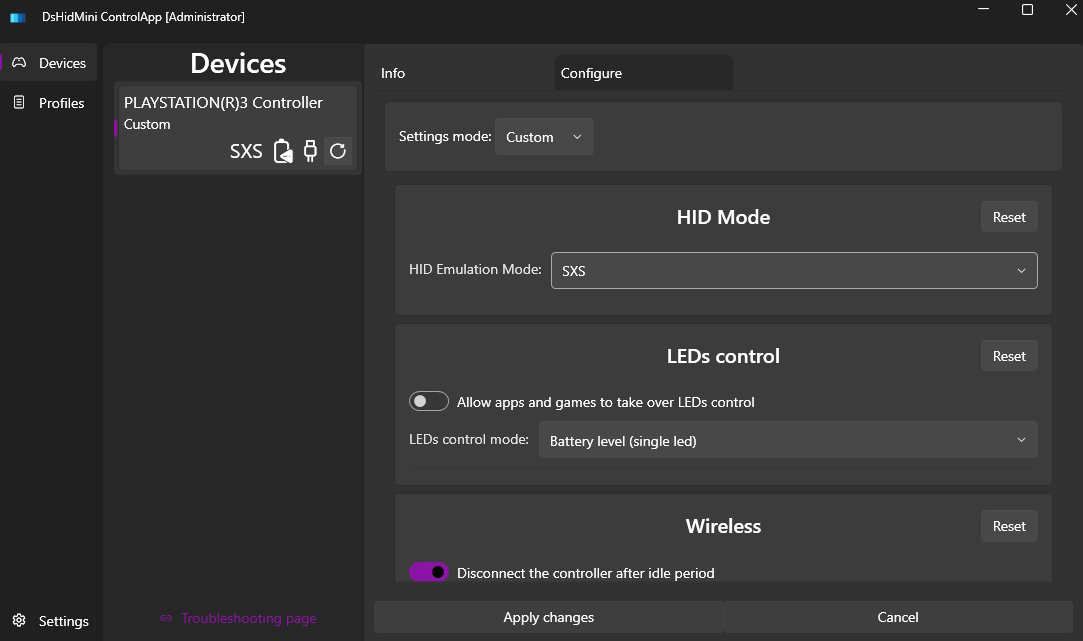
Next you need to set the HID Emulation Mode to SXS for the controller to work properly. To do this you need to download the DsHidMini driver ControlApp. Use the link below to download it.
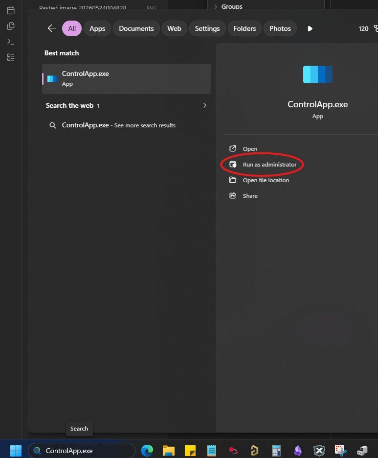
After installing ControlApp.exe run it as administrator. If you forgot where you downloaded it you should also be able to find it on Windows 11 by typing "ControlApp.exe" into your Search bar.
Next click on the Configure tab, on the dropdown menu for the Settings mode click Custom, and change the HID Emulation Mode to SXS through its dropdown menu, finally hit Apply changes. Make sure to unplug and replug the breadboard project to your PC.
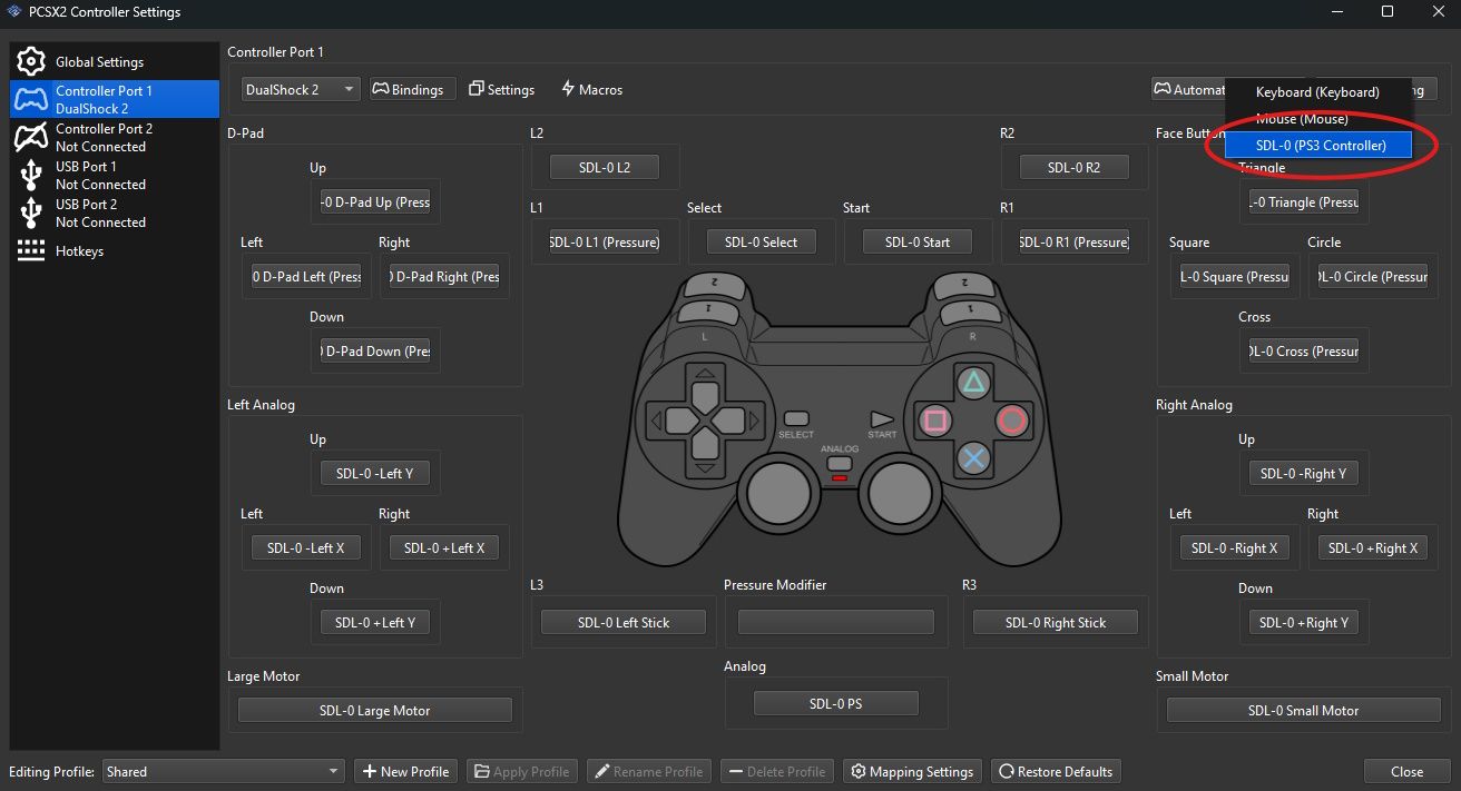
Now open PCSX2, go to Settings > Controllers. Click on Controller Port 1 on the sidebar and then on "Automatic Mapping". There should be an option for the controller you can click on.
If you want to test the pressure-sensitive buttons or rumble motors would recommend running padtest_ps2.elf on PCSX2. You can test rumble motors by holding down triangle and then by pressing D-Up or D-Down for the small motor or by pushing the left analog stick up or down for the large motor.
NOTE: When the PIC microcontroller sends the command (0x4F) to enable the pressure sensitive button mode on the DualShock 2 controller, it must poll the controller shortly afterwards, or the controller will exit pressure sensitive button mode. The timing of the polls after sending this command is stupidly finicky, it cannot be too soon or too far out. I've made a separate delay function in main.c for calibrating this timeframe so that it's just right, but there's a chance for other people building this project it'll fail. When it fails the values for each button will repeatedly switch from 0 to 255 and back, this is easy to see when running padtest_ps2.elf. If this happens recommend playing with the timing in the function shown below (right now it's set to Delay1KTCYx(39); which makes the microcontroller run through 39000 clock cycles doing nothing).
// Time delay function between polls, getting this time right can be fussy
void __delay_poll()
{
    Delay1KTCYx(39);
}
And that's it! There's still a few bugs such as the rumble motors turning on if you unplug and replug the controller while the PCSX2 is open, and the USB device not getting recognized if you plug in the breadboard project to your computer without the controller plugged in (to fix this unplug the USB and replug it). Moreover really looking forward to putting everything on a PCB and making a box for it in the future. This project was nearly a year in the making as I work full-time, if you have any questions please feel free to reach out and if you want DM me on Discord (farmerboy101_).
Sources
- https://www.waitingforfriday.com/?p=451
- https://docs.google.com/document/d/1XSrNVxOWOfCggHXhkQBapbmum18elYUx/edit
- https://hackaday.io/project/170365-blueretro/log/186471-playstation-playstation-2-spi-interface
- https://forum.allaboutcircuits.com/threads/interfacing-ps2-wireless-controller-with-a-pic-microcontroller.153348/
- [https://hades.mech.northwestern.edu/index.php/USB_Communication_using_PIC_microcontrollers](https://hades.mech.northwestern.edu/index.php/USB_Communication_using_PIC_microcontrollers
- https://eleccelerator.com/wiki/index.php/DualShock_3
- https://www.instructables.com/How-to-Interface-PS2-Wireless-Controller-W-Arduino/
- https://electronics.stackexchange.com/questions/52047/hid-descriptor-to-use-for-a-playstation-2-controller