The Switch Flicker
- Category:
- Projects
- Author:
- Ohad S. Farkash
- Date:
- 09/12/2024

A very specific issue has arisen in Durham's premierest (and only-est) non-profit makerspace, Splat Space. It is one which plagues me every time I leave and enter.
The light switch is not by the entrance.
Normally this wouldn't be such a big deal. Only Splat Space is not able to make serious modifications to the building. As such, some ingenious engineering was required to save the day.
Enter — the Switch-Flicker (known colloquially as the light-thing).
The plan is to create a servo controlled light switch flicking device which would sit atop the original light switch. Then, using those means inherent to backyard engineering, a controlling circuit will wire signals to the servo from afar.
To be fair, this isn't really a challenging project; it was a phenomenal excuse to use 3D printed parts, CNC machined wood, and some electronics, all in one go.
Summarized Mission Statement
As the polar selection of lighting the main chamber of this locale has hitherto been subject to great inconvenience on the behalf of our persons, I thus decree a new device be smithed. By means available within, and primarily materials of the space in question, a mechanical solution shall be derived which forever vanquishes this most unfortunate of dilemmas.
So say we all.
- Ohad Farkash
Onwards
I had debated many methods for moving the light switch, but only one promised simplicity. The arm of a servo would be rotationally fixed to the switch. However, there was a small hurdle - the two objects pivot from different points.
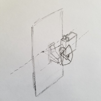
To solve this, the servo was given the ability to move up and down. This allows it to follow the linear movement of the switch as it changes position.
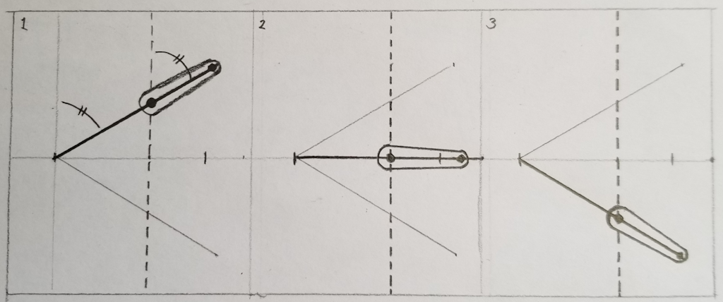
This sliding servo design also meant there could be some leniency when it came to dimensions, a plus when working with 3D printed parts.
Initially, the design allowed the user to manually move the switch. This was abandoned when it was determined that this would cause some undesirable effects on the switching end. At first the slot was removed, and the switch cover shortened. After some thought I decided to add a thinner slot, allowing for some extra diagnostic and manual override. Without the nub, it would still discourage manual movement of the switch.
I had some considerable difficulty getting this design to work. The servo had a tendency of applying force in directions that prevented the switch from fully actuating. One common issue saw the servo motor turn within its slot, rather than moving in a strictly linear manner.
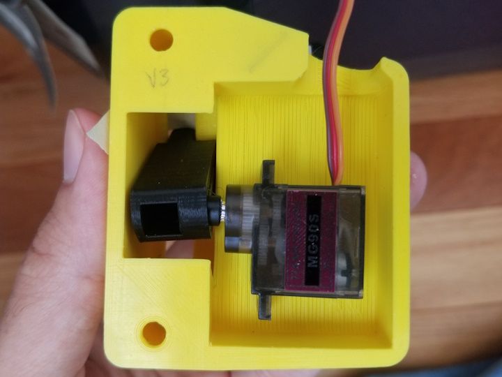
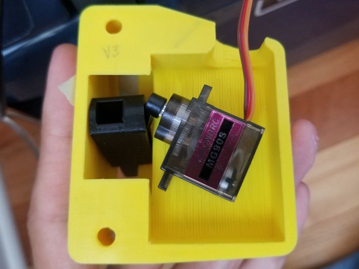
At first, I decided to make the servo a much closer fit to the rail so the bottom would be pressed against the housing. This didn't work.
The final solution was to create a guide rail that the servo would sit in. This meant that the servo's motion was restricted to only a single axis (up/down).
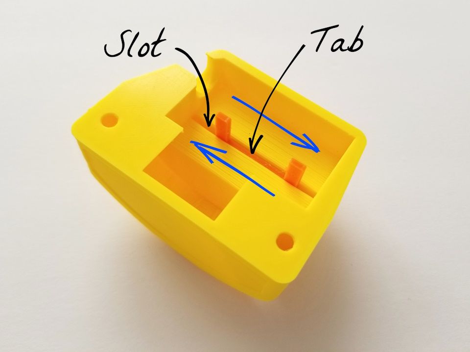
Blue arrows show the direction of motion.
And so, after much trial and error, the servo reliably actuates the switch! The doing of which is demonstrated in this short video:
Evolution
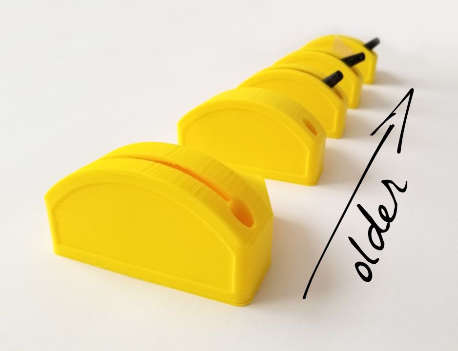
Iterations of the servo housing from newest (front) to oldest (back). A nice reminder that engineering is an iterative, creative process.
Artsy Engineering
To complete this device, the actuating unit had to be paired with a good user interface. For this I chose something that resembles a light switch, but is a little more interesting than a regular one. Because the mission of this project is to use those resources available at the makerspace, I chose a fun little toggle switch, and a nice piece of scrap wood.
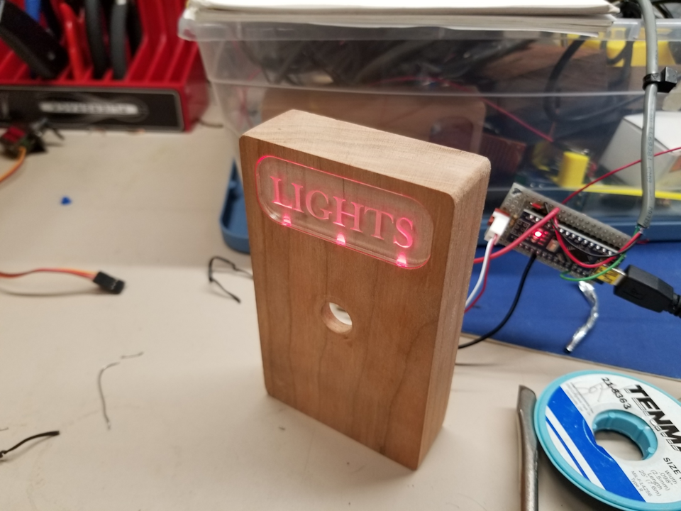
I also found some scrap acrylic and decided to have a small illuminated sign. This would help new members locate the switch in the dark room, and quickly ascertain its function.
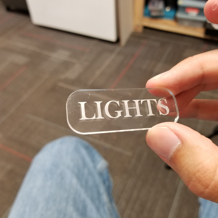
To create an enclosure out of wood, it was necessary to remove material from both sides. Doing this in a CNC machine was an interesting challenge. I was able to eventually succeed in aligning the two sides. The results looked fantastic!
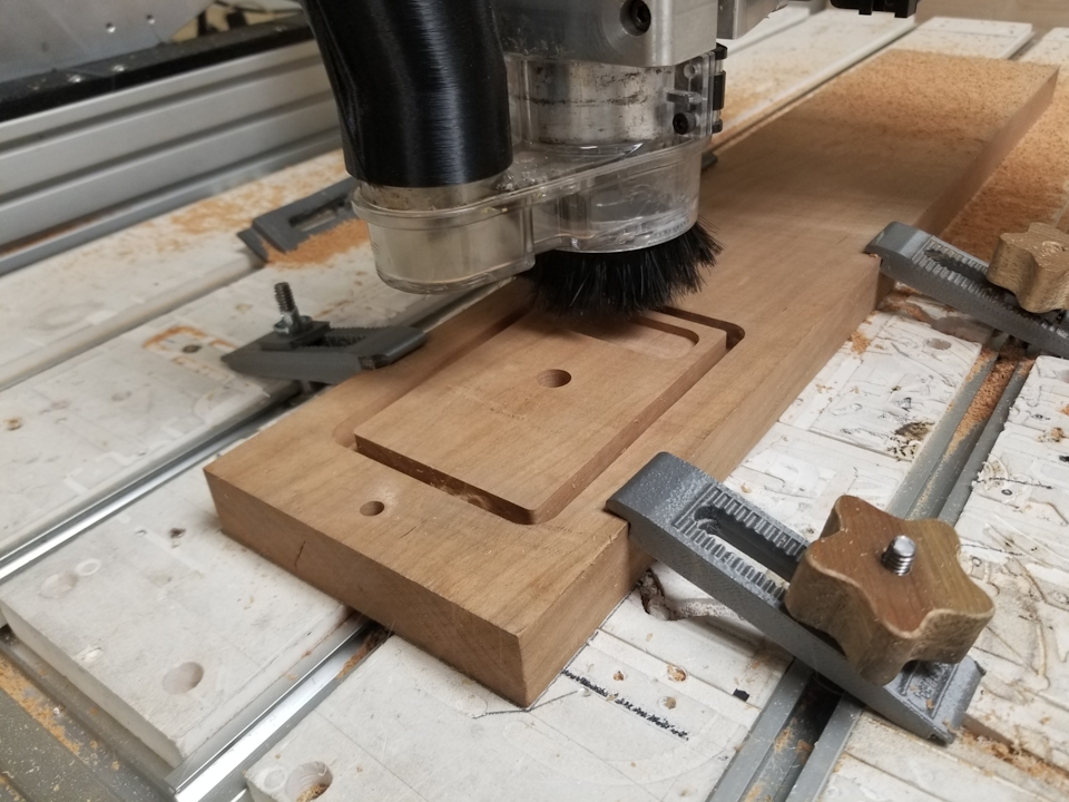
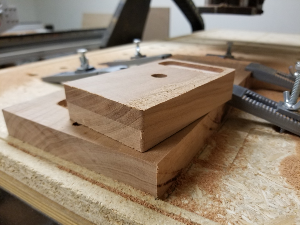
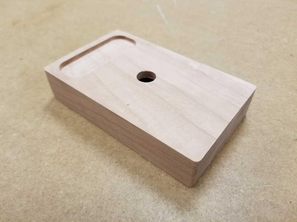
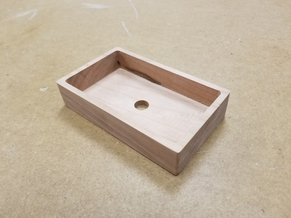
Although I started with a hard wood (type unknown), I ended with a nice piece of cherry. The advantage of using a wood that is not too hard is that the cuts are more accurate. This is important for properly fitting the acrylic.
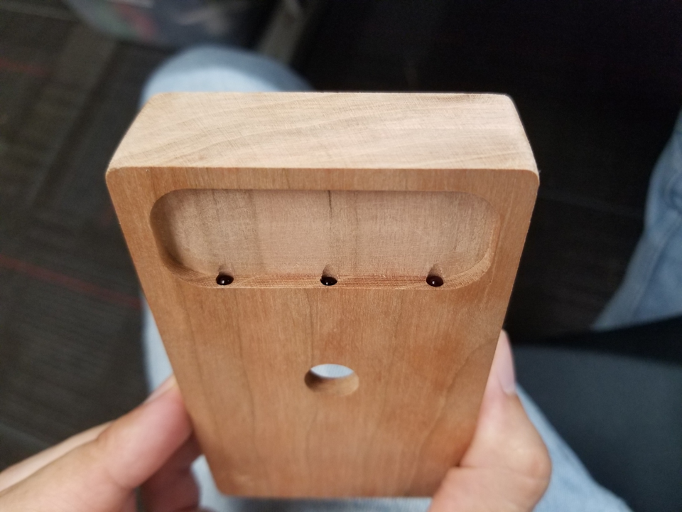
To mount the LED lights that would shine onto the acrylic sign, three small holes were drilled at a 15° angle from the surface of the box.
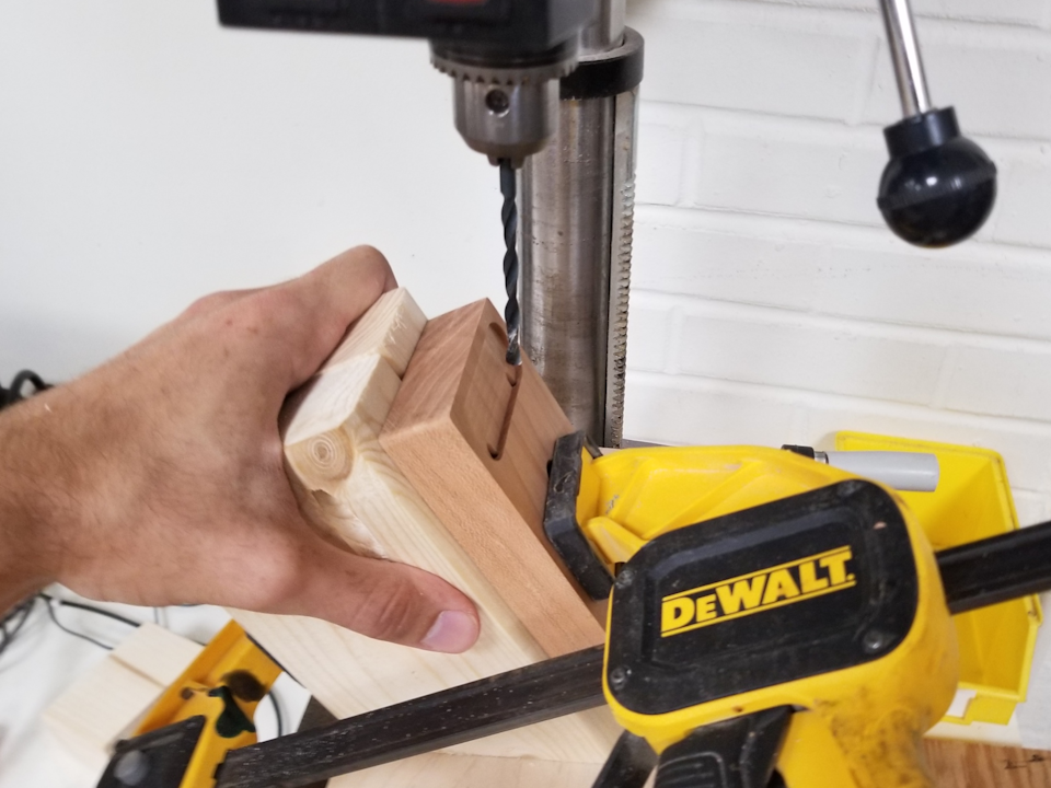
This would allow the 3mm LEDs to shine upwards at the sign. In the future, I would prefer having the lights shine from the top down. Either way, the sign was successfully illuminated.
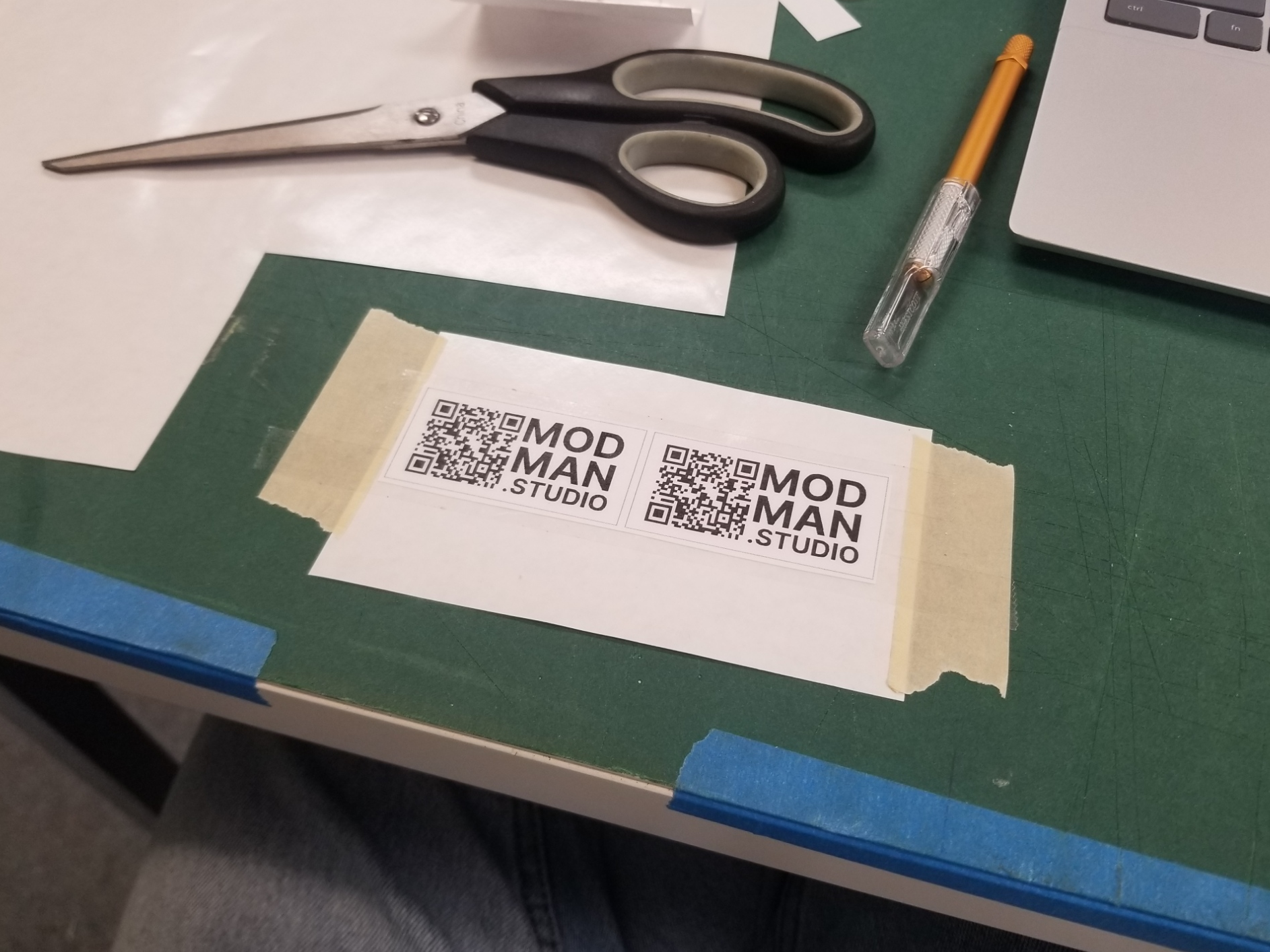
To finish everything off, stickers were added to both the switch box and the actuator. These, like everything else, were made using Splat Space resources; in this case, some double-sided tape, paper, and adhesive laminating film.
Electronics
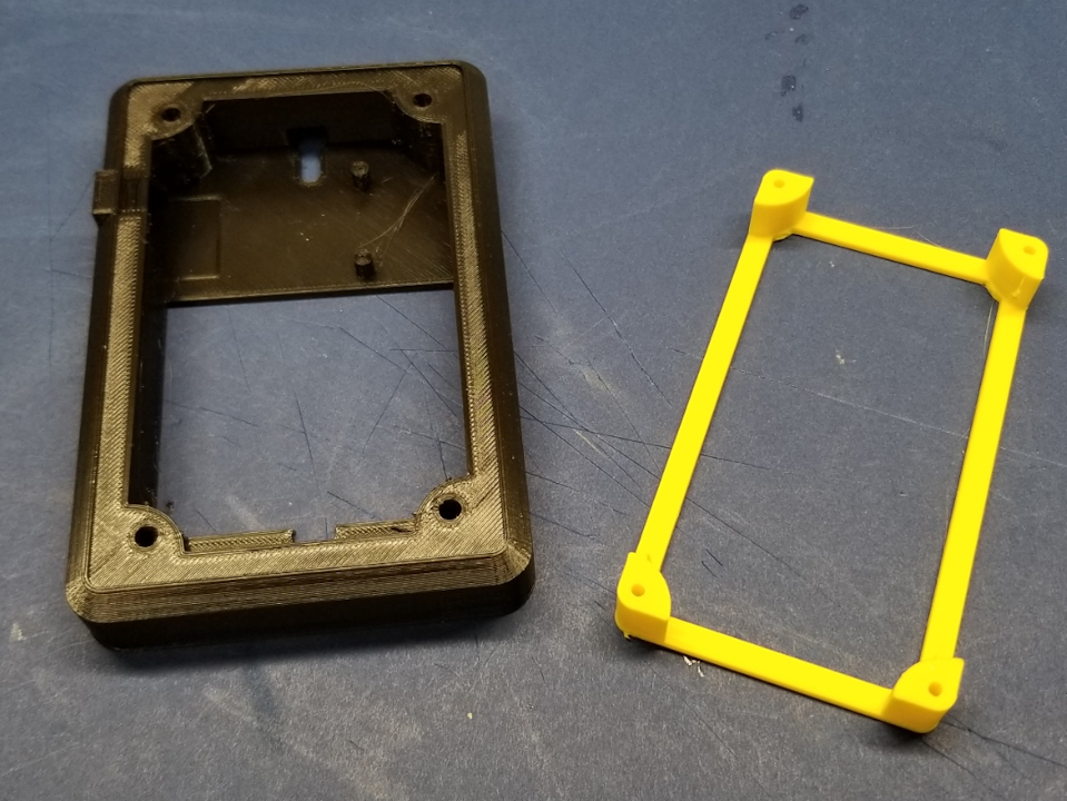
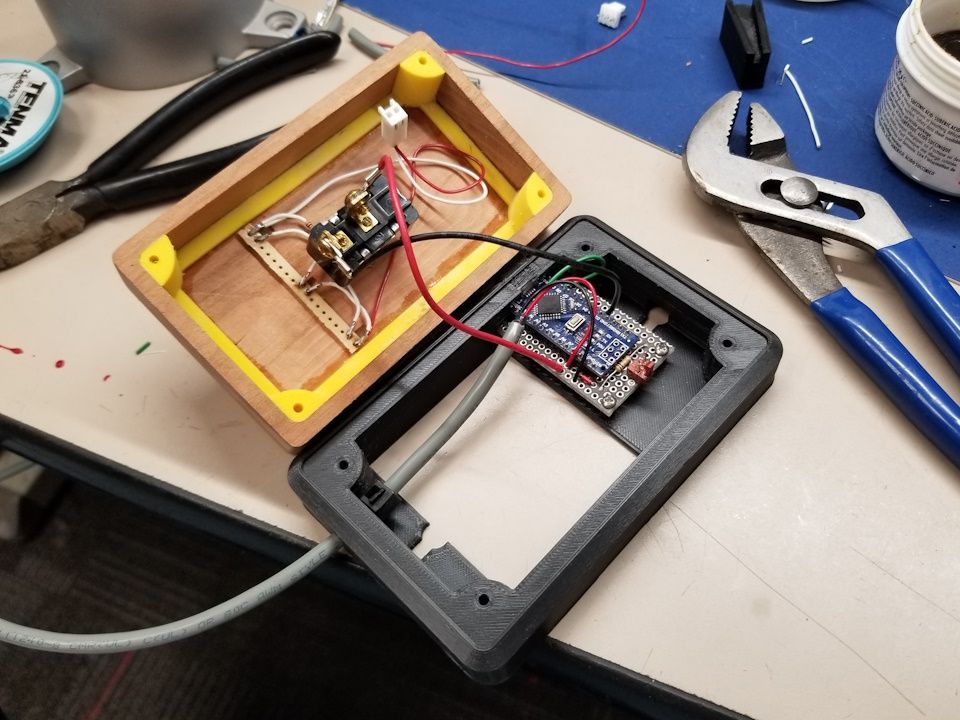
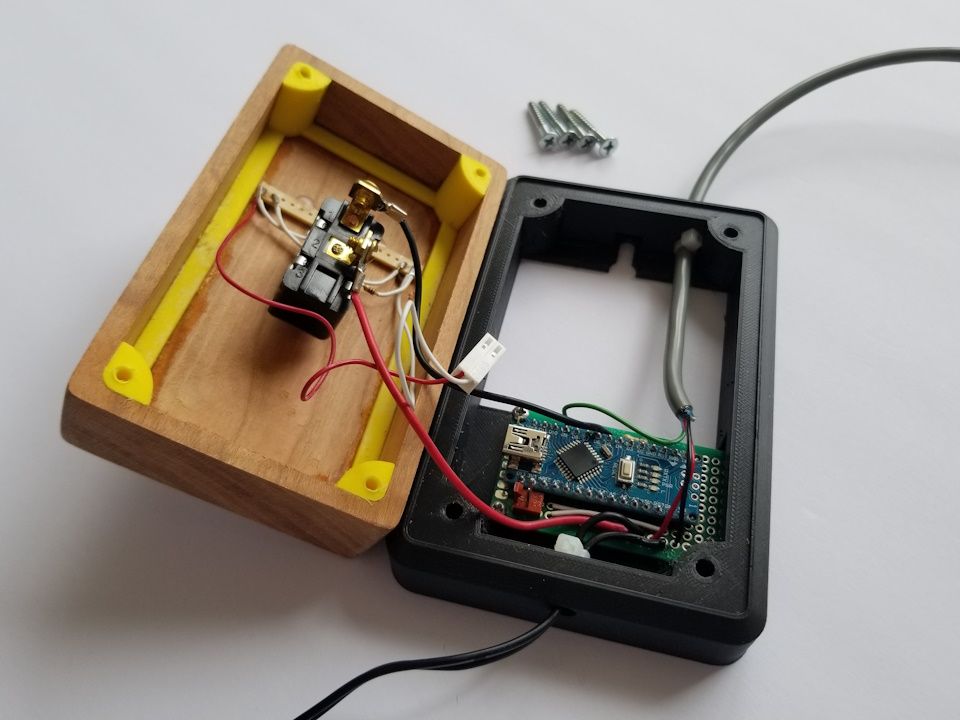
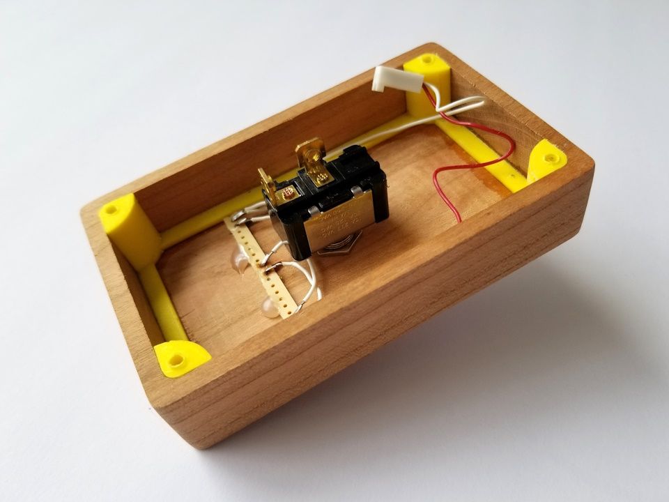
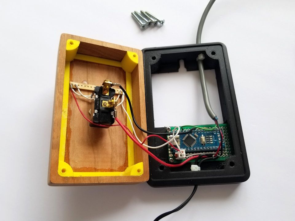
To house all the electronics, a frame was created for the switch box. The frame like the actuator was 3D Printed using PLA. To mount the wood box to the frame, a sub-frame would be glued into the box.
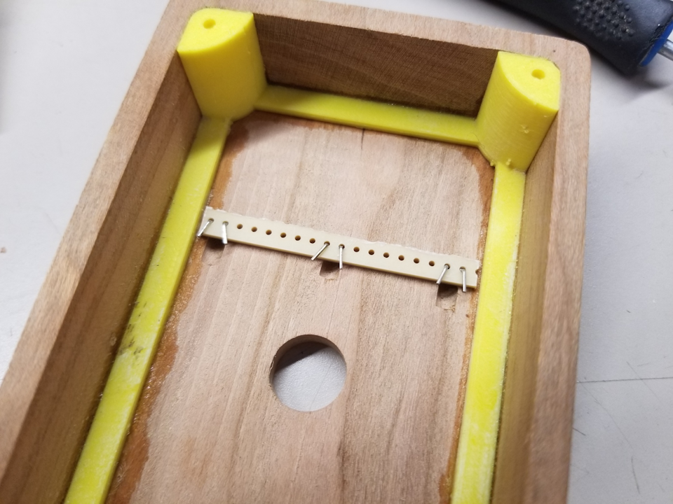
To mount the LEDs, a piece of perfboard was cut to fit. The LEDs were mounted and glued in place, then wired so that they would receive enough amperage to function. The LED bar was then hot-glued in place.
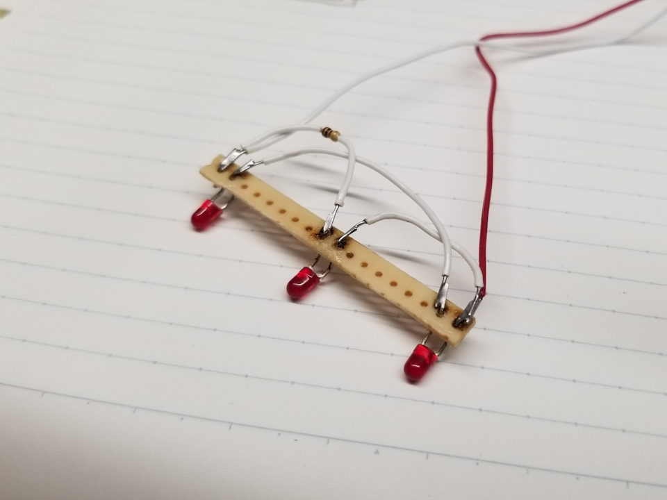
Notice the resistor only serves one line. This is because the other line chains two LEDs in parallel, thus reducing the current in the same manner as the resistor, I think...
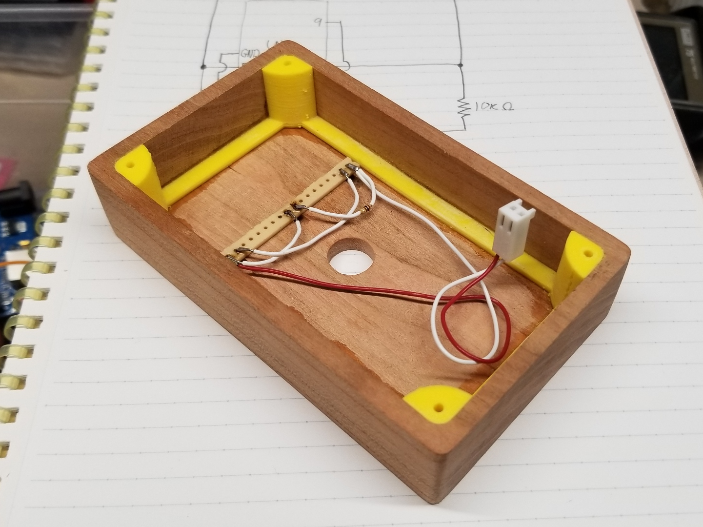
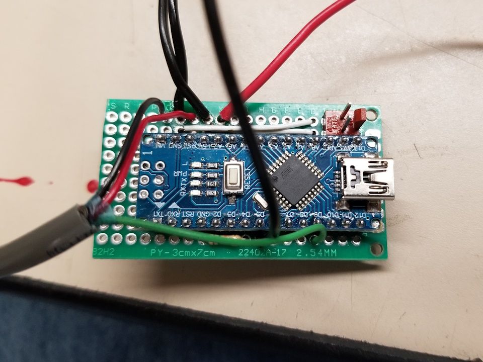
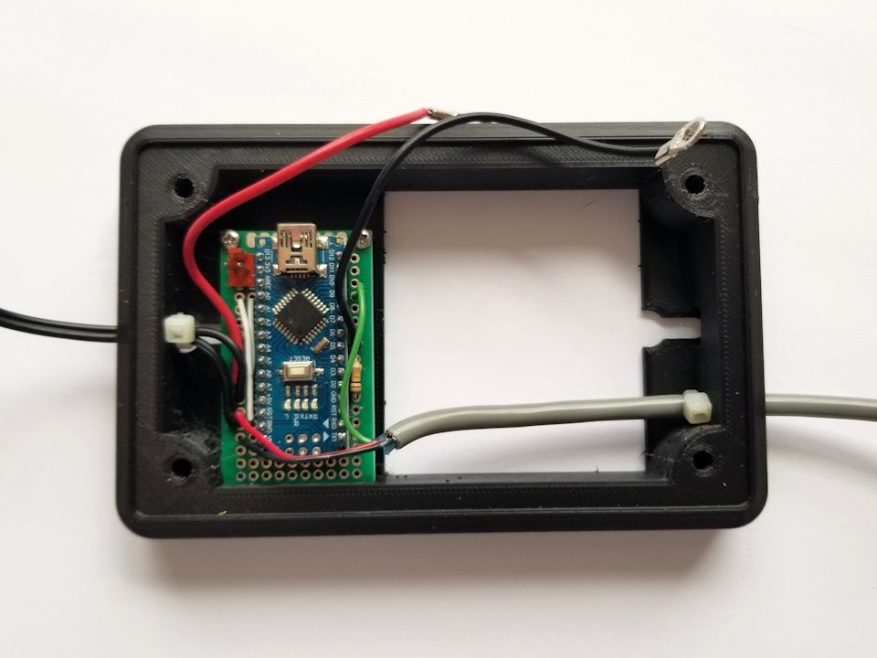
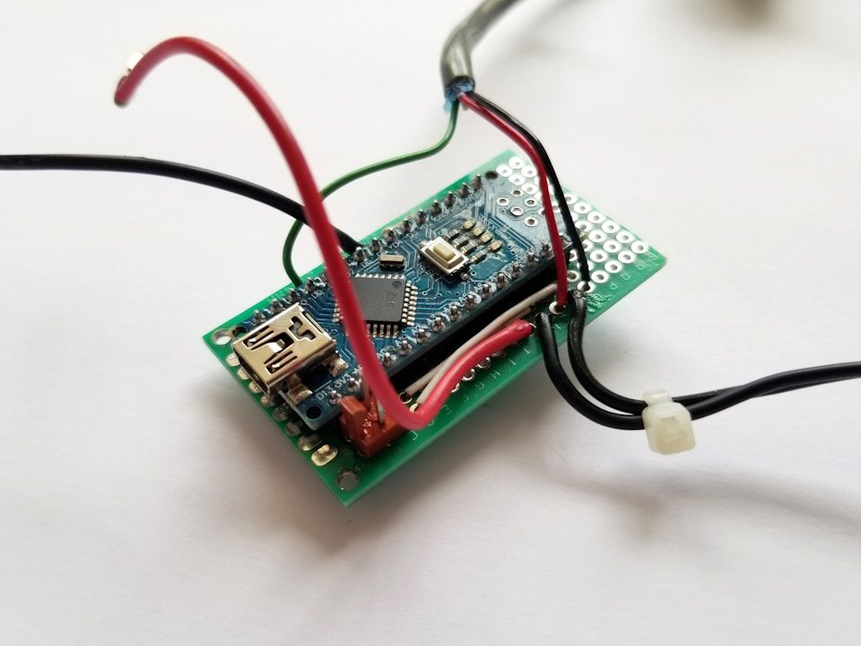
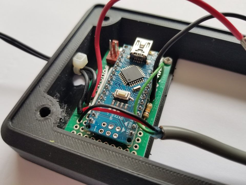
To drive the servo motor, an Arduino nano was chosen. The program checks the state of the switch using a digital pin. Depending on the state, the servo is sent commands to move to a specific angle. After a short time, the servo is shut down. This last step ensures that the servo does not overheat, as it may do when holding an angle continuously.
#include <Servo.h>

Servo servo;  // servo object controlls the servo

const int servoPin = 9;
const int buttonPin = 5;
int prevButtonState = 0;
int buttonState = 0;

void setup() {
  pinMode(buttonPin, INPUT);
}

void loop() {
  buttonState = digitalRead(buttonPin);
  if (prevButtonState != buttonState){
    servo.attach(servoPin);
    if (buttonState == HIGH) {
      servo.write(90+32);
      delay(15);
      servo.write(90+32);
      delay(15);
      servo.write(90+32);
      delay(15);
      servo.write(90+32);
      delay(15);
      servo.write(90+32);
      delay(15);
      servo.write(90+32);
      delay(15);
      servo.write(90+32);
    } else {
      servo.write(90-32);
      delay(15);
      servo.write(90-32);
      delay(15);
      servo.write(90-32);
      delay(15);
      servo.write(90-32);
      delay(15);
      servo.write(90-32);
      delay(15);
      servo.write(90-32);
      delay(15);
      servo.write(90-32); // what? too many times?
    }
    prevButtonState = buttonState;
    delay(1500);
    servo.detach();
  }
}
Those repeat commands are there in case the actuator gets snagged. Not sure if it's needed but I won't fix what ain't broke!
At first, the servo was powered by the Arduino's voltage regulator. I has assumed (wrongly) that the short burst needed to move the servo would not cause harm to the micro-controller.
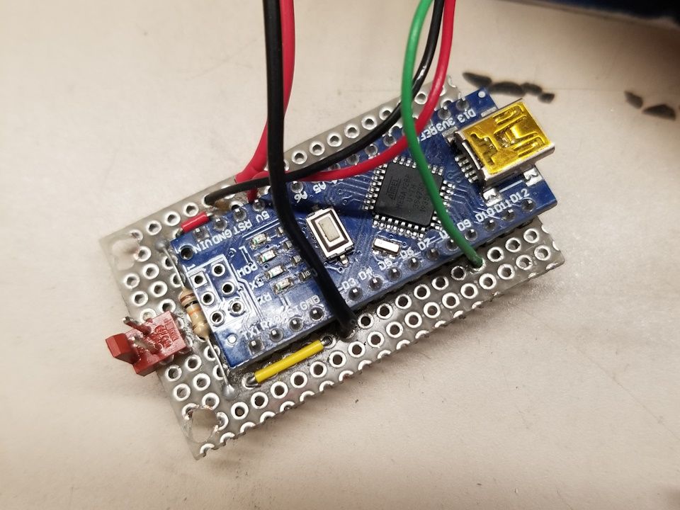
This resulted in some magic smoke.
After replacing the Nano, the wiring was changed so that most peripherals would be powered by the power supply directly. Being that the supply used could handle upwards of 2 Amps, I was no longer worried about the burnout.
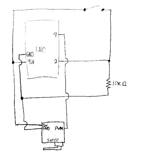
Old schematic where servo is powered by Arduino 5v output
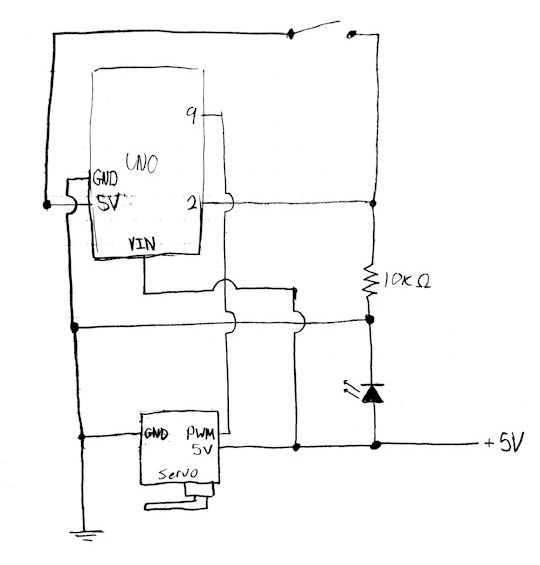
Revised schematic with independent power for servo.
To accommodate this new setup, the frame was modified as well.
Take a Step Back and be Proud
After all of that work, I gave my creation a nice photo shoot.
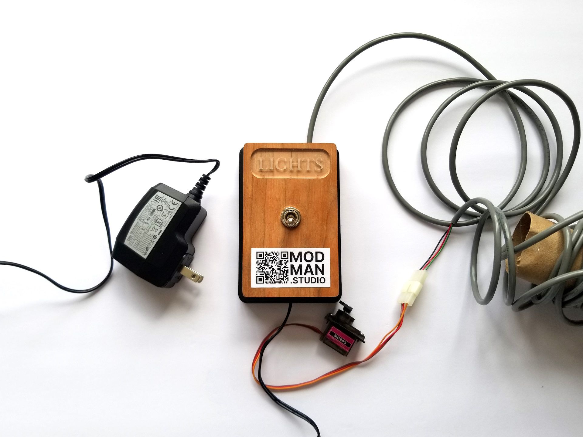
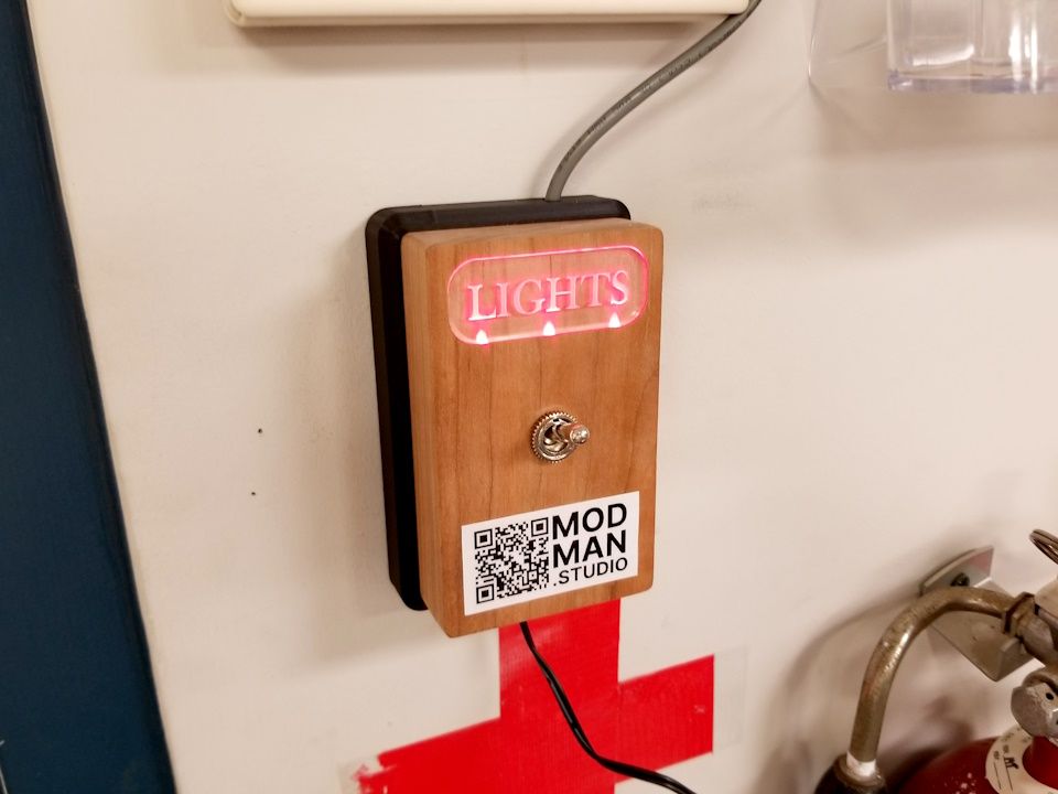
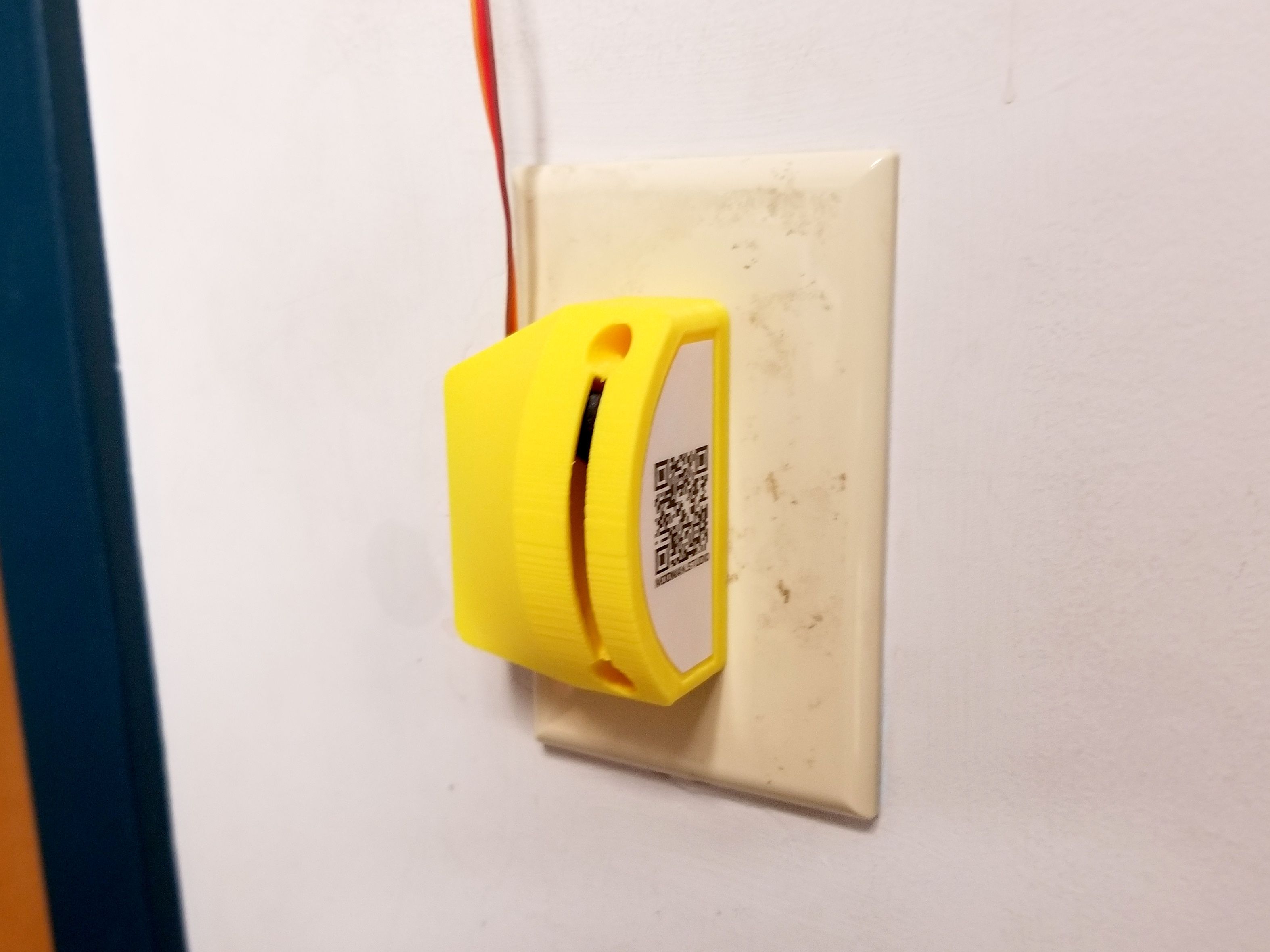
Finally, it was time to install the Switch Flicker. After anchoring two screws, the switch box was able to slide firmly in place.
Next the wires were snaked up to the drop ceiling, and then out on the other end. The actuator was mounted over the the light switch, and the servo was connected.
The final result: